Antenna
Antennas are an integral part of any Radio Frequency (RF) communication systems. By definition an antenna is a transducer, a device used to transform RF signals traveling on a conductor (wire, waveguide for example) into an electromagnetic wave in free space and vice versa (this is due to the fact they are reciprocal devices, retaining the same characteristics regardless if they are transmitting or receiving).
As antennas are resonant devices, they can only operate efficiently in a certain frequency bandwidth, for a certain central frequency (frequencies), which is called tuning.
In order to work the frequency in the sytem, the antenna is tuned to must be the same the rest of the system is operating on, in order to receive/transmit adequately. This relates to antenna matching.
Last but not least, an antenna emits the radiation it converts in a certain in space in a certain way (shape), which has a graphical representation called radiation pattern.
![]()
Antenna basics
Before delving into detail into what types of antenna there are and what their performance is we need to explain a number of terms that pertain to antenna characteristics. This will allow us to efficiently describe antenna performance and compare different types.
Input Impedence: In order to have efficient transfer of energy (power) between the antenna, cable (when applicable) and radio device, they need to have the same impedance. Typically transceivers (radio devices) are designed with 50 Ohm impedance (also the case for LoRa/LoRaWAN), thus the antenna must also have impedance of 50 Ohm. If the aforementioned is not the case there will be the need for a matching circuit, otherwise the mismatch will cause reflection of the signal (energy) and will result in losses (decreased efficiency).
Return Loss: This relates to impedance matching, as it is a way of quantifying the resulting energy loss. It is expressed in logarithmic ratio (measured in dB) and is the value of the ration of the power reflected by the antenna (due to impedance mismatch) to the total power fed to the antenna via the transmission line (cable).

VSWR: Another way to express the return loss (more commonly used parameter) is to use the variations of the voltage along the transmission line (highest to lowest ratio). The relationship between VSWR and Return loss is:

Bandwidth: The bandwidth of an antenna refers to the range of frequencies over which the antenna can operate correctly. As a rule of thumb the bandwidth is considered to be the frequency area for which the antenna VSWR is less than 2:1.
Different antennas have different bandwidths.
Directivity: Antennas are mean to transfer the signal between the receiver and transmitter, thus they need to be able to focus the energy in a particular and also receive better from a particular direction. This would make it possible for an antenna to transfer the energy more efficiently especially if the two devices are static with respect to each other.
In cases where the positions change, it is generally not optimal to have an antenna with high directivity, as the direction where one would want to transmit optimally changes with the position of the transmitter/receiver. In such situation antennas that radiate equally in all directions are best, which are called omni-direction (omni) antennas.
Gain: As gain is not a quantity that can be defined in absolute terms it is a dimensionless ratio, which is given in reference to a standard antenna (expressing how much better the performance is compared to the standard antenna).
The two most common antennas used as reference when talking about gain are:
Isotropic antenna
This type of antenna radiates equally in all directions. This is a purely theoretical construct, such antenna does not exist in practice, however it is very useful when used as reference for real antennas. A real antenna of any type will radiate more energy in a certain directions and less in others. Since an antenna is a passive device it can not create energy, thus its total radiated power is the same as of an isotropic antenna.
So, the gain of the antenna in a given direction is the amount of energy radiated in this direction as compared to an isotropic antenna, given that both antennas have the same signal source. The maximum gain (most interesting parameter) is the gain in the direction where the antenna radiates the most power.
This gain is expressed in dBi (dB compared to an i-sotropic antenna). For example 3dBi gain means that that the gain is 3dB compared to an isotropic antenna (twice as much in linear scale).
Dipole antenna
The other antenna used for standard comparison is the half-wave dipole. This comparison in gain is expressed in dBd (dB compared to a d-ipole antenna). An antenna gain of 3dBd means that the antenna has 3dB gain more compared to a dipole antenna.
Far Field Conditions: Antennas are mean to transfer the signal between the receiver and transmitter, thus they need to be able to focus the energy in a particular and also receive better from a particular direction. This would make it possible for an antenna to transfer the energy more efficiently especially if the two devices are static with respect to each other.
In cases where the positions change, it is generally not optimal to have an antenna with high directivity, as the direction where one would want to transmit optimally changes with the position of the transmitter/receiver. In such situation antennas that radiate equally in all directions are best, which are called omni-direction (omni) antennas.

Free Space Propagation: In order to have this condition met, there must be a direct line of sight between the two antennas, meaning there must be no obstacle in-between the two. In addition, it is recommended for the first Fresnel zone to be free of obstacles (in order to avoid negative effects due to superposition of direct and reflected signals). We would not go into detail on how to calculate Fresnel clearance, however for the purposes of gaining basic understanding one could look at Figure 3 in order to visualize approximately how big the first Fresnel zone is:

Radiation Pattern: The radiation (antenna pattern) represents the way the antenna radiates in various directions at a constant distance (this is normally in the far field area), this is also the reception pattern since it also relates to the receiving properties of the antenna.
The radiation pattern is three-dimensional, however it is most commonly represented in a two-dimensional slice of the pattern in the horizontal or vertical plane. Most commonly the two-dimensional patterns are presented in polar coordinate format, as it is easier to visualize.
Let us look at an example dipole antenna pattern shown in its three-dimensional variant in Figure 4:

Figure 4: 3D radiation of a dipole antenna
.png?s=21d0602387165e90d0fc392980fc90fc)
Figure 5: 2D radiation of a dipole antenna
Beamwidth: The term antenna beamwidth usually means the half-power beamwidth. In order to determine this parameter one would need to know the peak radiation intensity (highest gain point) and take the points on its side where its level drops to half the value. The angular distance between these two points is defined as the beamwidth.
Sidelobes: Antennas are not perfect, so they can't radiate all the energy only in the direction of the main lobe. The energy peaks that are not in the main lobe direction are called side lobes. They are commonly specified in dB down from the main lobe.
Nulls: This is a spot in the antenna radiation pattern that falls between two lobes and the affective radiated power at this point is minimal. These nulls are useful as reception in their direction is minimal and they can be used to suppress interfering signal coming from a given direction.
Polarization: In short, this is the orientation of the electric field of the electromagnetic wave (energy) that is radiated/received by the antenna. Without going into details we will mention there are 3 types of polarization in general: vertical, horizontal, circular (right-handed, left-handed). As an example omnidirectional antennas are vertically polarized, always.
Polarization Mismatch: As was the case with Impedance, in order to have a maximum power transfer between two antennas they must have the same polarization. When their polarization is not the same the will be a reduction in the transferred power between the two. Thus, make sure both antennas have the same polarization and their spatial orientation is the same in order to ensure optimal transmission/reception.
Type of Antennas
Let us classify antennas based on one of the following: frequency/size, directivity, physical traits, and application.
Frequency/Size: Antennas are tuned to different frequencies as different RF systems operate in different parts of the Spectrum. The wavelength being different for different frequencies means antennas will also differ in size as it is related to the wavelength they need to operate at.
For example, all things being equal, a 900MHz antenna for LoRaWAN will have a wavelength of 33cm, where as a 2100MHz antenna for cellular will have a wavelength of 14cm, which is more than 2 times smaller.


Directivity: As mentioned before the antenna could be omnidirectional, radiating equally in all directions (Dipole, Ground plane).
Another option is the sectorial antenna (mainly used in cellular) that radiates primarily in an area, where the beam width can be 60 or 180 degrees for example.
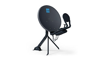
Directional antennas are also widely used (Radio relays) as they have a very narrow beam width (smaller than 30 degrees usually), which results in a large gain and improved range. An example would be the Yagi antenna, the horn antenna, the patch antenna, the parabolic dish antenna, etc.
Physical traits: There are differnet constructions, we will not go into details, however some notable ones are patch antennas made via PCB substrate in the for of metallic circuitry. The monopole which is basically a wire, there are also flexible antennas built on ceramics.
Based on their construction some antennas can be outdoor capable and some indoor only.
Application: It is most common in RF systems (which IoT and LoRaWAN fall within too) to have one of two applications: Base station, Point-to-point.
The first type is for broadcasting/wide area reception and is usually an outdoor capable omnidirectional antenna, or a combination of several sectorial antennas.
The point-to-point antennas are usually directive as they connect two devices that are for most cases very far apart, stationary and require a lot of gain to establish the link.